Introduction: The Imperative for Grid Modernization
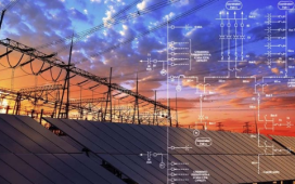
A smart grid is an electricity network that uses digital technology, sensors, and automation
to monitor and control the flow of power from generation to consumption. Unlike the traditional one-way power flow (from power plants → consumers), smart grids allow two-way communication between utilities and end-users.
Key Features:
– Real-time monitoring of power consumption
– Integration of renewable energy (solar, wind, hydro)
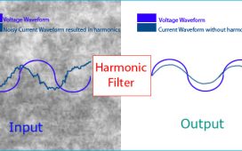
– Improved reliability with fault detection and self-healing networks
– Demand-side management to balance supply and demand
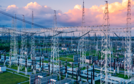
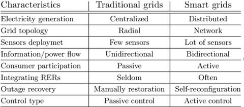
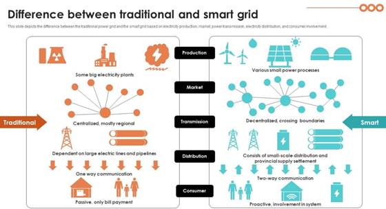
The electrical grid is one of the most extensive and critical infrastructures ever built. For over a century, it has reliably delivered power from large, centralized generation plants (coal, nuclear, hydro, gas) to consumers through a hierarchical, one-way network of transmission and distribution lines. However, this aging architecture is showing its limitations.
The smart grid is an evolution, not a replacement, of the existing grid. It is the integration of advanced digital communication, information technology, and automation into every aspect of the power system—from generation and transmission to distribution and consumption. The core principles of the smart grid are:
- Bidirectional Flow: It allows for both electricity and data to flow in two directions, enabling a dynamic and responsive system.
- Distributed Intelligence: Control and decision-making are not limited to a central command center but are distributed throughout the network, allowing for localized, autonomous responses to changing conditions.
- Enhanced Security: The network is designed with built-in security features to protect against cyber threats and ensure the integrity of data and operations.
- Sustainability: It enables the large-scale integration of renewable energy and promotes energy efficiency through demand-side management.

Limitations of the Traditional Grid
- Opaque and Electromechanical: Utilities often lack real-time visibility into grid conditions, especially at the distribution level. Outage reports primarily come from customer calls, not sensors.
- Passive and Inefficient: The grid is designed for top-down power flow, making it difficult to integrate two-way power flows from rooftop solar, wind farms, and other Distributed Energy Resources (DERs).
- Vulnerable to Cascading Failures: Localized faults can escalate into widespread blackouts due to a lack of automated, rapid isolation and reconfiguration capabilities (e.g., the 2003 Northeast blackout).
- Aging Infrastructure: Much of the equipment is nearing or has exceeded its intended lifespan, leading to increased failure rates and maintenance costs.
- Limited Consumer Engagement: Traditional meters only measure total consumption, providing no granular data or means for consumers to participate in grid stability.
Defining the Smart Grid: A Paradigm Shift
The smart grid is an umbrella term for the modernization of the entire electricity delivery system. It is not a single technology but a integration of many, characterized by:
- Two-Way Flow of Electricity and Information: Power flows from generation to load, and information flows back, enabling dynamic control.
- Widespread Use of Digital Technology: Replacing analog and electromechanical systems with intelligent digital devices.
- Integrated Communications: Pervasive, robust, and secure communication networks connecting all components.
- Automation and Advanced Control: Using data and software to optimize grid operations in real-time.
Core Technological Pillars
Advanced Metering Infrastructure (AMI)
AMI is the foundational technology that enables two-way communication and data exchange between utilities and consumers.
- Smart Meters: These digital meters replace traditional analog ones. They record energy consumption at regular, short intervals (e.g., every 15 minutes) and transmit this data to the utility automatically. Key functions include:
- Real-time Data Collection: Provides granular data on energy usage, allowing for accurate billing and personalized insights for consumers.
- Remote Services: Enables utilities to remotely connect or disconnect service, perform meter readings, and update firmware.
- Integration with Home Area Networks (HANs): Allows smart meters to communicate with in-home devices like smart thermostats, appliances, and home energy management systems.
- Communication Networks: AMI relies on a robust and secure communication network to transmit data. Technologies used include:
- Wireless Mesh Networks: A self-healing, peer-to-peer network where each smart meter acts as a relay, passing data to the central collection point.
- Power Line Communication (PLC): Uses the existing power lines to transmit data, eliminating the need for separate communication infrastructure.
- Cellular Networks: Provides a reliable and widespread communication channel, particularly in rural areas.
- Meter Data Management Systems (MDMS): This software platform at the utility’s end collects, validates, and stores the massive amounts of data from the smart meters. MDMS is crucial for billing, data analytics, and providing real-time insights to grid operators.
Core Objectives and Benefits
The transition to a smart grid is driven by a compelling set of benefits:
- Improved Reliability and Resilience: Faster outage detection, isolation, and restoration (self-healing). Reduced frequency and duration of outages.
- Enhanced Efficiency: Reduced technical losses through better voltage control and optimization. Enables Conservation Voltage Reduction (CVR).
- Increased Integration of Renewable Energy: Seamlessly manages the variability and distributed nature of solar and wind power.
- Empowered Consumers: Provides customers with detailed energy usage data and tools (via web portals and smart thermostats) to manage their consumption and costs.
- Support for Electrification: Provides the foundational infrastructure needed to support the mass adoption of electric vehicles (EVs) and electric heating.
Architectural Framework of the Smart Grid
To understand the complexity of the smart grid, it is essential to view it through architectural models that define its components and their interactions.
- Key Domains: Generation, Transmission, Distribution, Consumption
The physical grid can be divided into functional domains:
- Generation: Now includes both bulk generation and distributed generation.
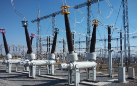
- Transmission: High-voltage network moving power over long distances. Smart grid tech here includes PMUs and FACTS devices.
- Distribution: Medium and low-voltage network delivering power to end-users. This is where most smart grid modernization (AMI, DA, VVO) is focused.
- Consumption: The end-use customers (residential, commercial, industrial) equipped with smart meters and energy management systems.
The Critical Role of Two-Way Communication
The seamless flow of information is what makes the grid “smart.” Data from millions of sensors must be aggregated, communicated, processed, and acted upon in near-real-time.
Core Technological Components
The smart grid is built upon several pillars of advanced technology.
- Sensing and Measurement: The Grid’s Nervous System
- Advanced Metering Infrastructure (AMI)
AMI is the most visible smart grid component. It is a full system of smart meters, communication networks, and data management systems that enables two-way communication between utilities and customers.
- Components:
- Smart Meter: A solid-state digital meter that records consumption (often in intervals of 15 or 60 minutes) and can receive commands (e.g., remote disconnect).
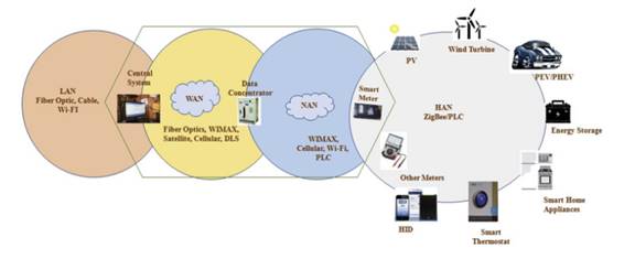
- Communication Network: A combination of Home Area Network (HAN), Neighborhood Area Network (NAN), and Wide Area Network (WAN).
- Meter Data Management System (MDMS): A central database that validates, edits, and stores the vast volumes of meter data for billing and analytics.
- Functionality: Enables remote meter reading, time-based pricing, outage notification, and remote connect/disconnect.
- Phasor Measurement Units (PMUs) and Wide-Area Monitoring Systems (WAMS)
PMUs, or “synchrophasors,” are high-speed sensors placed on transmission lines. They measure the electrical phasor (magnitude and phase angle) of voltage and current, synchronized to a common time source (GPS) with microsecond accuracy. - Application: This allows for a precise, system-wide view of the grid’s state. WAMS use data from many PMUs to detect grid stress, oscillations, and instability in real-time, allowing operators to take corrective action to prevent blackouts.
- Smart Sensors and Fault Circuit Indicators (FCIs)
These are devices deployed on distribution feeders and in substations.
- Smart FCIs: Traditional FCIs simply flag a fault with a mechanical flag. Smart FCIs communicate the fault location and details back to the control center via wireless networks, drastically speeding up outage response.
- Distribution Sensors: Monitor parameters like voltage, current, power factor, and temperature on lines and transformers.
- Advanced Control Methods: The Grid’s Brain
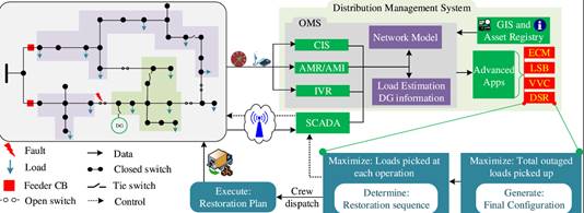
- Distribution Management Systems (DMS)
A DMS is a suite of software tools that acts as the central brain for distribution grid operations. It uses a real-time model of the distribution network to optimize performance.
- Functions include: Volt-VAR Optimization (VVO), Fault Location, Isolation, and Service Restoration (FLISR), and switching sequencing for maintenance.
- Outage Management Systems (OMS)
An OMS uses data from smart meters (last gasp signals), customer calls, and field crew reports to predict the location of an outage and dispatch crews efficiently. Integrated with a DMS and GIS, it provides a comprehensive view of outage events.
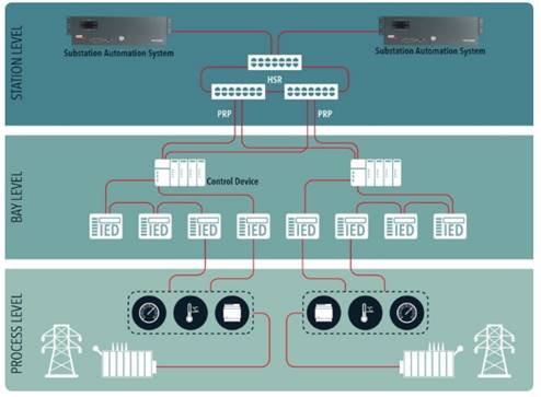
Substation Automation and IEC 61850
Modern substations are automated using Intelligent Electronic Devices (IEDs) like protective relays and controllers. The international standard IEC 61850 is critical as it defines a common data model and communication protocols for substation devices, ensuring interoperability between vendors and simplifying engineering.
Power Flow and Energy Management
- Flexible AC Transmission Systems (FACTS)
FACTS devices are power electronics-based systems that control AC transmission parameters (voltage, phase angle, impedance) to enhance the controllability, stability, and power transfer capability of the grid. Examples include Static VAR Compensators (SVC) and Unified Power Flow Controllers (UPFC).
- Advanced Power Electronics
These are the interfaces for modern energy resources.
- Inverters: Convert DC power from solar panels and batteries to AC power for the grid. Smart inverters can also provide grid services like voltage support and frequency regulation.
- HVDC (High-Voltage Direct Current): Used for efficient long-distance bulk power transmission and connecting asynchronous AC grids.

Integrated Communication: The Grid’s Circulatory System
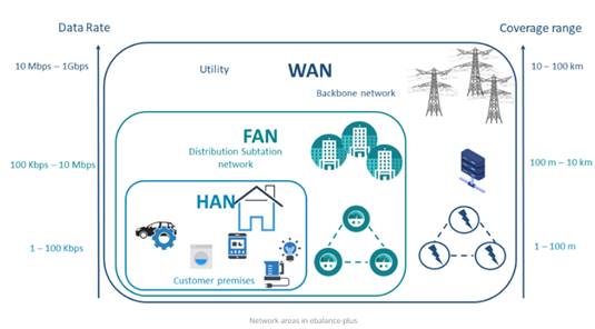
Communication networks are layered:
- Home Area Network (HAN): Connects devices within a home (smart thermostat, inverter, EV charger) to the smart meter. Technologies: Zigbee, Wi-Fi, Z-Wave.
- Neighborhood Area Network (NAN): Aggregates data from 500-5000 smart meters. Technologies: RF Mesh (e.g., IEEE 802.15.4g), Cellular (4G/5G), Power Line Carrier (PLC).
- Field Area Network (FAN): Connects distribution automation devices (reclosers, capacitors, FCIs). Technologies: Cellular, Licensed RF (e.g., 900 MHz), Wi-SUN.
- Wide Area Network (WAN): The backhaul network connecting NANs and FANs to the utility’s data center. Technologies: Fiber optics, Microwave, Cellular.
Key Applications and Functionalities
The integration of the components above enables transformative applications.
- Integration of Distributed Energy Resources (DERs)
DERs include rooftop solar, battery storage, electric vehicles, and small-scale wind. The smart grid manages their two-way power flow.
- Challenges: Reverse power flow can cause voltage violations (overvoltage) on distribution feeders.
- Solutions: Advanced inverters that can absorb reactive power to regulate voltage. DMS algorithms that can actively manage DER output to maintain grid stability.
- Volt-VAR Optimization (VVO) and Conservation Voltage Reduction (CVR)
This is a major source of efficiency gains.
- VVO: Automatically adjusts voltage regulators and capacitor banks to maintain voltage within the optimal band (e.g., 114-126V) while minimizing losses.
- CVR: A technique that deliberately lowers voltages to the lower end of the acceptable band. Because many loads are constant impedance (e.g., incandescent lights, heaters), this reduces both energy consumption (kWh) and demand (kW). VVO enables safe and effective CVR.
- Fault Location, Isolation, and Service Restoration (FLISR)
This is the “self-healing” capability.
- Fault Detection: A fault occurs. Smart sensors and FCIs instantly detect it.
- Fault Location: The DMS/OMS analyzes data to pinpoint the fault’s location.
- Isolation: The DMS sends commands to automated switches (reclosers, sectionalisers) upstream and downstream of the fault to isolate the smallest possible section.
- Service Restoration: The DMS then re-energizes the healthy sections of the feeder by closing alternate paths from other substations or feeders. This can happen in minutes, often before customers even call to report an outage.
Predictive and Condition-Based Maintenance
Instead of maintaining equipment on a fixed schedule, utilities use sensor data (transformer temperature, load, dissolved gas analysis) to predict failures before they happen. This maximizes asset life and prevents costly unplanned outages.
 Samsung Galaxy Tab S10+ Plus – Buy on Amazon
4.6 Enhanced Cybersecurity for Critical Infrastructure
The increased connectivity creates a larger attack surface. Cybersecurity is paramount and must be designed in from the start.
- Threats: Data theft, ransomware, remote manipulation of control systems to cause blackouts.
- Mitigations: Network segmentation, strict access controls, encryption of data in transit and at rest, continuous monitoring for anomalies, and adherence to standards like NIST IR 7628.
Communication Protocols and Standards
Interoperability—the ability of devices from different manufacturers to exchange information and work together—is achieved through standards.
- IEC 61850: For substation automation and beyond (now extending to DERs).
- DNP3 (Distributed Network Protocol) and IEC 60870-5: Widely used for SCADA communications between control centers and field devices.
- Common Information Model (CIM): An abstract model that defines the standard “language” for representing power system components (e.g., a breaker, a transformer) and their relationships. This allows different utility applications (DMS, OMS, EMS) to exchange data seamlessly.
- IEEE 2030.5 (Smart Energy Profile 2.0): A standard for communication between the smart grid and consumer appliances/EVs.
Economic Benefits for Stakeholders
- For Utilities:
- Reduced Operational Costs: Automation reduces the need for manual meter readings and dispatching crews for routine maintenance.
- Asset Optimization: Better data allows utilities to operate their existing infrastructure more efficiently and defer costly upgrades.
- Revenue from New Services: Utilities can offer new services like demand response programs and real-time energy data portals to consumers.
- For Consumers:
- Empowered Participation: Consumers can monitor their energy use in real-time, allowing them to make informed decisions to save money.
- Time-of-Use (TOU) Pricing: Smart meters enable TOU pricing, where electricity is more expensive during peak hours and cheaper during off-peak hours. This encourages consumers to shift their energy use, reducing their bills.
- Reliability: Fewer and shorter power outages due to the grid’s enhanced resilience.
Conclusion
The transition to a smart grid is not a mere upgrade; it is a fundamental re-architecting of a century-old system for a new era. It is a complex, long-term undertaking that integrates advanced sensing, control, communication, and computing technologies. While significant challenges remain, particularly in cybersecurity and regulation, the benefits are undeniable: a grid that is more resilient, efficient, sustainable, and consumer-centric. The smart grid is the essential enabling infrastructure for a clean energy future, forming the backbone upon which decarbonization, decentralization, and digitalization of the energy sector will be built. Its continued evolution will be one of the most critical engineering endeavors of the 21st century.