1. Introduction
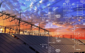
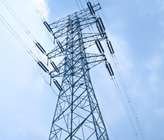
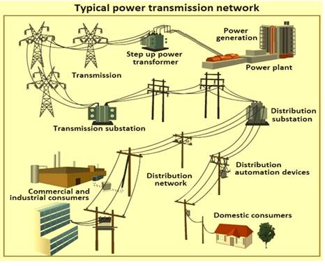
Overhead transmission lines form the backbone of modern power systems. They connect generating stations to substations and deliver electricity across cities, industries, and rural regions.
Their design and construction require multidisciplinary knowledge — electrical, civil, and mechanical engineering — and adherence to international standards such as IEC 60826, IEEE 738, and IS 802.
This guide explores in detail the principles behind electrical design, mechanical strength, insulation coordination, tower configuration, maintenance, and future innovations in overhead line systems.
2. Basic Components of Overhead Transmission Lines
Each transmission line consists of several integral parts that ensure mechanical stability and safe current flow.
2.1 Conductors
Conductors carry electrical power. The most common types are:
| Type | Description | Voltage Range |
| AAC (All Aluminium Conductor) | Economical, corrosion-resistant, used for short spans | LV–MV |
| AAAC (All Aluminium Alloy Conductor) | Higher tensile strength, lighter, less sag | MV–HV |
| ACSR (Aluminium Conductor Steel Reinforced) | Steel core provides strength; ideal for long spans | HV–EHV |
| ACSS (Aluminium Conductor Steel Supported) | Designed for higher operating temperature | EHV |
| HTLS (High-Temperature Low-Sag) | Advanced composite materials, used in uprating | 220 kV + |
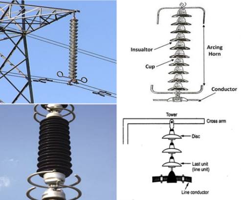
2.2 Insulators
Insulators isolate the live conductor from grounded structures.
- Pin Insulators – up to 33 kV
- Suspension Insulators – for 66 kV and above
- Strain Insulators – used at line terminations and angles
Modern polymer insulators (composite type) offer improved mechanical performance and contamination resistance.
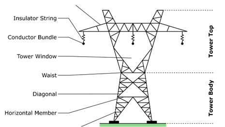
2.3 Supports and Towers
Towers maintain clearances and support mechanical loads.
Types include:
- Wooden or RCC poles: distribution networks
- Steel tubular poles: urban or constrained areas
- Lattice towers: 110 kV–800 kV transmission
2.4 Hardware and Accessories
Line fittings include clamps, spacers, vibration dampers, arcing horns, jumpers, and suspension assemblies — all ensuring mechanical reliability.
3. Electrical Design Considerations
▶︎ GUIDE TO OVERHEAD TRANSMISSION LINE DESIGN, CONSTRUCTION, AND MAINTENANCEElectrical design determines conductor sizing, insulation level, and voltage regulation.
3.1 Design Parameters
- System voltage and frequency
- Maximum load current
- Power factor and load diversity
- Line length and allowable voltage drop
- Lightning impulse withstand level (BIL)
3.2 Line Resistance and Power Loss
Power loss per phase:

Reducing resistance (by using larger cross-sectional area or low-resistivity materials) minimizes energy loss.
3.3 Voltage Regulation
For long lines, voltage drop is significant. Regulation is improved by reactive power compensation using shunt capacitors or reactors.
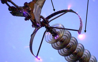
3.4 Corona Discharge
Corona occurs when the electric field intensity exceeds air’s dielectric strength.
Minimized by:
- Using larger-diameter conductors
- Employing bundled conductors at EHV levels
- Maintaining adequate phase spacing
4. Mechanical Design and Load Calculations
Mechanical design ensures towers and conductors can withstand environmental and operational loads.
4.1 Forces Acting on a Tower
- Dead Load: weight of conductors, insulators, and tower
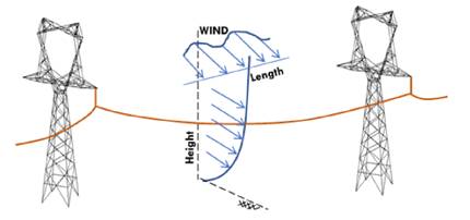
- Wind Load: calculated as per IEC 60826 or IS 802 Part 1
- Ice Load: in cold regions, increases conductor weight
- Unbalanced Load: during conductor break or maintenance
4.2 Sag and Tension
Proper sag prevents excessive mechanical stress and ensures safe ground clearance.

where= sag (m),
= weight per meter,
= span,
= tension.
Temperature effect:

Example:
For a 200 m span, ,
:
4.3 Wind and Ice Loading
Wind pressure N/m² (where V = wind speed m/s).
For 120 km/h wind, .
Ice load adds additional downward force; combined loads are considered using vector summation.
5. Tower Design and Configuration
5.1 Tower Types
- Suspension towers – support straight runs
- Tension towers – used at angles or terminations
- Transposition towers – balance line inductance
- River-crossing towers – extremely tall, high mechanical load
5.2 Tower Geometry
- Phase spacing: depends on voltage (e.g., 6–12 m at 400 kV)
- Ground clearance: minimum 7 m at 400 kV (per IEC 60071)
- Shield wire height ensures lightning protection angle ≤ 30°
5.3 Foundation Design
Foundation type depends on soil bearing capacity.
Common foundations:
- Pad and chimney
- Pile foundation (for marshy soils)
- Raft or grillage (for rocky terrain)
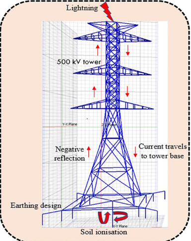
6. Earthing and Lightning Protection
Lightning is a major cause of faults on overhead systems. Effective grounding and shielding are essential.
6.1 Shield Wires
Ground wires at tower tops intercept direct strikes.
- Shielding angle typically 30°–45°
- Multiple wires used at higher voltages
6.2 Tower Footing Resistance
Should be below 10 Ω (optimum 3–5 Ω).
Methods:
- Earthing rods or counterpoise conductors
- Bentonite or salt enhancement for high-resistivity soil
6.3 Surge Arresters
Installed at line terminals and substations to limit transient overvoltages.
7. Electrical Clearances and Right-of-Way
Adequate clearance ensures safety and reliability.
| Voltage Level | Min. Phase–Ground (m) | Phase–Phase (m) | Ground Clearance (m) |
| 11 kV | 0.7 | 0.3 | 4.6 |
| 33 kV | 1.0 | 0.6 | 5.5 |
| 132 kV | 2.0 | 1.8 | 6.1 |
| 220 kV | 2.8 | 2.5 | 7.0 |
| 400 kV | 3.5 | 3.0 | 8.5 |
Right-of-way (ROW) is governed by CEA and NESC regulations — typically 35 m for 400 kV lines and 52 m for 765 kV.
8. Construction and Installation
8.1 Survey and Route Selection
- Avoid dense urban and forest zones
- Minimize angle points and crossings
- Conduct soil resistivity and topography surveys
8.2 Tower Erection
Sequence:
- Stub setting and foundation
- Tower body erection
- Cross-arm installation
- Stringing of insulators and conductors
8.3 Conductor Stringing
Performed under controlled tension using winch and tensioner.
Sag is adjusted per temperature and span length.
8.4 Quality Checks
- Torqueing of bolts
- Insulation resistance measurement
- Line alignment verification by drone/survey equipment
9. Testing, Commissioning, and Maintenance
9.1 Pre-Commissioning Tests
- Continuity and phase verification
- Tower footing resistance measurement
- Visual inspection and mechanical alignment
9.2 Routine Maintenance
- Visual Inspection: corrosion, damage, vegetation encroachment
- Thermography: detect hotspots or loose joints
- Insulator Washing: in polluted zones
- Hardware Tightening: bolts, clamps, and jumpers
- Ground Wire Testing: corrosion and continuity
9.3 Condition Monitoring Technologies
- Drone & LiDAR scanning for structural integrity
- IoT sensors for tension and temperature
- Digital twin for predictive maintenance
9.4 Common Failures
| Failure Type | Cause | Prevention |
| Conductor snapping | Over-tension, fatigue | Proper sag, inspection |
| Flashover | Pollution, lightning | Washers, arresters |
| Corrosion | Salt environment | Galvanizing, coating |
| Loose fittings | Vibration | Dampers, periodic tightening |
10. Case Study: 220 kV Double-Circuit Line Design
To illustrate the application of design standards, consider a 220 kV D/C line across mixed terrain.
Key Data
- Power: 150 MVA per circuit
- Span: 350 m average
- Conductor: ACSR “Zebra”
- Wind speed: 120 km/h
- Terrain: Semi-urban
Design Highlights
- Sag: 3.8 m at 40 °C
- Tower Height: 34 m
- Insulation: 9 × 160 kN discs per string
- Grounding: Counterpoise with 3 Ω resistance
The design complies with IEC 60826, IS 802, and CEA (Safety) Regulations 2023, achieving a reliability index above 99.98%.
11. Environmental and Safety Considerations
Transmission projects require environmental approvals and community safety measures.
- Maintain minimum distance from buildings and roads.
- Use bird diverters and aerial markers in ecological zones.
- Conduct electromagnetic field (EMF) assessment (< 5 kV/m at ROW edge).
- Noise level < 55 dB (A) for 400 kV lines.
Regular community awareness programs enhance public acceptance.
12. Future Trends and Innovations
12.1 Advanced Materials
- HTLS conductors (Invar, GAP, Carbon Core) for uprating existing corridors
- Composite towers with FRP or hybrid members reduce corrosion
12.2 Smart Grid Integration
IoT sensors and AI analytics enable real-time load monitoring, fault detection, and preventive maintenance.
12.3 Digital Design
Use of BIM, PLS-CADD, and GIS mapping tools optimize alignment and clearance analysis.
12.4 Renewable Integration
Overhead lines are being adapted for hybrid corridors, transmitting both solar and wind farm outputs.
13. Conclusion
The design and maintenance of overhead transmission lines demand a balance between cost, performance, and safety.
Compliance with IEC, IEEE, and IS standards ensures mechanical robustness and electrical reliability.
With the rise of HTLS conductors, smart sensors, and drone-based inspection, the future of transmission infrastructure is more intelligent, sustainable, and resilient than ever.