Filter Design
• Basics of Harmonic Filters, what they are, what they do
• Configuration Options
• Metal-Enclosed
• Open Air
• E-House
• Key Filter Ratings (V, I, Ih, Qeff, Tuning Point, etc.)
• How is harmonic current rating is determined
• Filter Types, Topology of each, advantages/disadvantages of each
• Notch
• HP (Damping factor)
• C-HP (Damping factor)
• Single/Multi-stage
• Tuning calculation (calculating Xeff, L, C, R)
• Component selection
• Capacitor Rating Procedure, applicable standards
• Heavy Duty Vs. Standard Duty (beware of claims), Specification, Vendor Review
• Tuning Reactor Rating Procedure, applicable standards
• Types: Air-Core | Iron-Core (Advantages/Disadvantages, Specification, Vendor Review)
• Damping Resistor Rating Procedure, applicable standards, types, # of series elements, specification, vendor review
• Switching Device (Breaker/Switches)
• Typical Protection
• Capacitor protection (internally fused vs. externally fused)
• Blown Fuse Detection
• Reactor Protection
• Overload protection / thermal protection
• Resistor Protection
• Short Circuit Protection (50/51 phase/ground), arc flash
• Over-voltage, Vthd/Ithd, Over-Temperature, Fan failure
• Typical Control
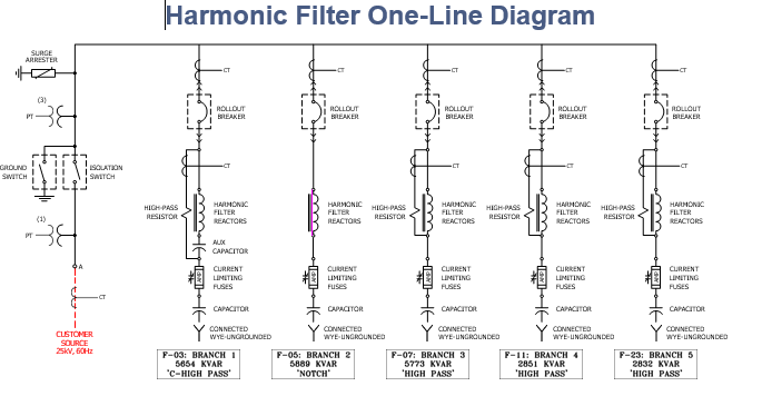
Filter One-Line Diagram
Harmonic Filters – Purpose & Uses
Purpose:
• Correct Power Factor (Reactive Compensation)
• Usually to avoid power factor penalties or comply with interconnect agreement
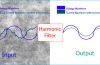
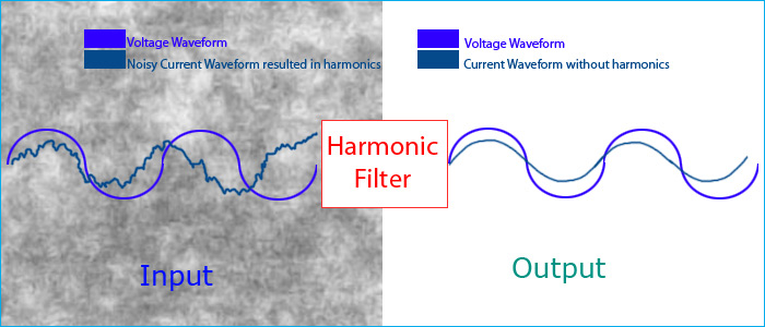
• Reduce Harmonic Current / Voltage Distortion
• By providing a low impedance path for
harmonic currents
• To Become compliant with harmonic standards
• IEEE 519
• IEC 61000-3-2 (EN 61000-3-2)
• Many others
• Prevent Harmonic Resonance
• Harmonic filters installed for the prevention of resonance are often called “de-tuned” capacitor banks.
• Applied when high-pulse drives
Harmonic Filters Are:
• Most Simply Stated –
• A capacitor bank with a tuning reactor
• The inductive reactance is a fraction of the capacitive reactance of the capacitor bank. As a result, they are, in many ways, a capacitor bank.
Main Parameters of Filter Ratings:
• Reactive Power Rating (KVAR / MVAR, 3-Phase Value)
• Usually based on reactive power requirement of load
• May be determined by harmonic duty requirements
• Voltage, based on system voltage (KVLL)
• Insulation Level (KV)
• BIL / 1 Minute Withstand
• Based on standard rating for voltage class of equipment
+pollution level, + elevation, + consideration for increased
reliability and arc flash mitigation
• Tuning Point (Hertz or Harmonic Number, i.e. 282 Hertz or 4.7th Harmonic for 60 Hertz System
• Filter Type (Notch, C-HP, HP)
• For C-HP, HP
• Damping Factor (R/Xinductor at tuning frequency)
• Resistor Rating (Ohms, KW)
• Fundamental Current Rating, I1, (Amps), at 10% Over-voltage
• Harmonic Current Ratings (Amps), Include all significant harmonics Under worst case conditions
• I5, I7, I11, I13…. etc. (be very conservative)
Harmonic Filter Ratings Determined:
• Power System Studies
• Load Flow Analysis
• Determines reactive power rating of filter (MVAR)
• Harmonic Analysis
• Determines filter tuning
• Determines expected harmonic current flow into filter branch(s)
• Filter type (Notch, C-HP, HP)
• Based on above studies, L, R, C Filter Parameters, and reactive power ratings are determined. The equipment specification is not normally developed from the study.